


Yaskawa America Inc. Home
Welcome to Yaskawa

Welcome to Yaskawa
Yaskawa is the leading global manufacturer of variable frequency drives, servo systems, machine controllers, and industrial robots. Our standard products, as well as our tailor-made solutions, are well known for outstanding quality and reliability.
Visit Yaskawa at Automate 2026

Visit Yaskawa at Automate 2026
Explore the future of automation in Chicago at our Booth# S-202 from June 22-25, 2026.
Compass 2 Now Available!

Compass 2 Now Available!
Compass 2 is the CNC software solution for iCube Control, combining industrial PC scalability for user interface and path planning with real-time motion and logic control of the iC9200, delivering an optimized CNC solution. Learn More
GA501 AC Microdrive

GA501 AC Microdrive
Ethernet-Ready, Out of the Box - With embedded dual-port Ethernet and support for all major industrial Ethernet protocols, the GA501 eliminates the need for extra hardware, reduces installation time, and simplifies system design.
Introducing the iQpump605

Introducing the iQpump605
Your complete pumping solution for constant pressure, flow, booster systems, lift stations, and more. Choose from Enclosed Configured or Enclosed Bypass packages, available in UL Type 1, 12, or 3R cabinets, with essential pump features.

GA800 600V Product Line Expansion

Sigma-X Product Line Expansion

Your Total Pumping Solution
Build a career at Yaskawa as part of a team that brings great energy to every challenge, every day. Be appreciated. Be supported. And, enjoy every opportunity to learn, grow, and succeed. Join our team!

Yaskawa at Automate 2026

Engineering Spotlight: Viral Robot Goalie

Yaskawa Drives Made in the USA
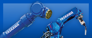
Yaskawa takes industrial automation to new levels through robotics. Our Motoman brand of robotic arms, part positioners, and easy-to-program controllers enables you to automate applications that were not thought possible just a short time ago. Visit Motoman.com for the latest in industrial robotics.